Are you tired of dealing with faulty electrical connections or wondering why your device isn’t working? Knowing how to test for continuity with a multimeter can save you time and frustration.
This simple skill is essential for anyone who wants to troubleshoot electrical circuits, whether you’re a DIY enthusiast or a professional electrician. Imagine the confidence you’ll feel when you can pinpoint the exact location of a break or short in a circuit.
In this guide, you’ll learn step-by-step how to effectively use a multimeter to test for continuity, ensuring your electrical projects run smoothly and safely. Let’s dive in and empower you with the knowledge to solve those pesky electrical mysteries!
Credit: learn.sparkfun.com
Multimeter Basics
Understanding how to use a multimeter can be incredibly empowering, especially when you’re trying to solve electrical mysteries. Multimeters are versatile tools that measure various electrical properties, and knowing their basics can transform the way you approach repairs and diagnostics. Whether you’re testing continuity or measuring voltage, understanding your multimeter is crucial to getting accurate readings.
Understanding Multimeter Functions
Multimeters come with several functions that might seem overwhelming at first. But once you get the hang of it, it becomes second nature. A typical multimeter can measure voltage, current, and resistance. It can also test for continuity, which is essential when checking if a circuit is complete.
Have you ever used the wrong setting on your multimeter and wondered why your readings are off? This is a common mistake when you’re unfamiliar with the functions. Knowing which setting to use saves you time and frustration. For instance, to test continuity, you typically use the setting that looks like a sound wave or diode symbol.
Safety Precautions
Before you dive into testing, consider your safety first. Multimeters, while safe, can be hazardous if not used correctly. Always ensure your multimeter is in good condition and that leads are properly insulated. Frayed wires can cause unexpected shocks.
Why risk your safety when a simple check can prevent accidents? Always test a multimeter on a known live circuit to ensure it’s functioning correctly. This practice helps avoid false readings that could lead you to make wrong conclusions about circuit health.
Are you wearing protective gear? Goggles and gloves are a must when dealing with electrical components. Ensuring your workspace is dry and free from unnecessary objects can prevent accidents.
With these basics in mind, testing for continuity becomes a straightforward process. So, are you ready to dive into using your multimeter effectively? The next time you pull out your multimeter, remember these tips and stay safe while getting accurate results.
Setting Up Your Multimeter
Testing for continuity with a multimeter ensures electrical connections are intact. Turn the dial to the continuity setting. Touch the probes to the circuit or wire. A beep indicates a complete path.
Setting up your multimeter correctly is crucial before you start testing for continuity. This preparation ensures accurate readings and prevents potential damage to your device. Missteps here could lead to faulty conclusions or even harm your multimeter.Selecting The Right Mode
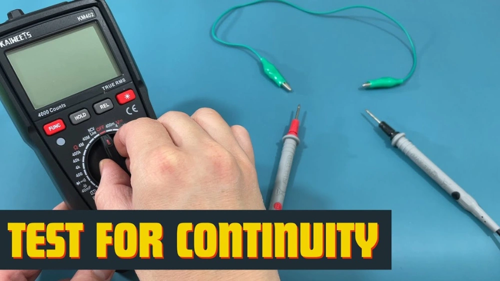
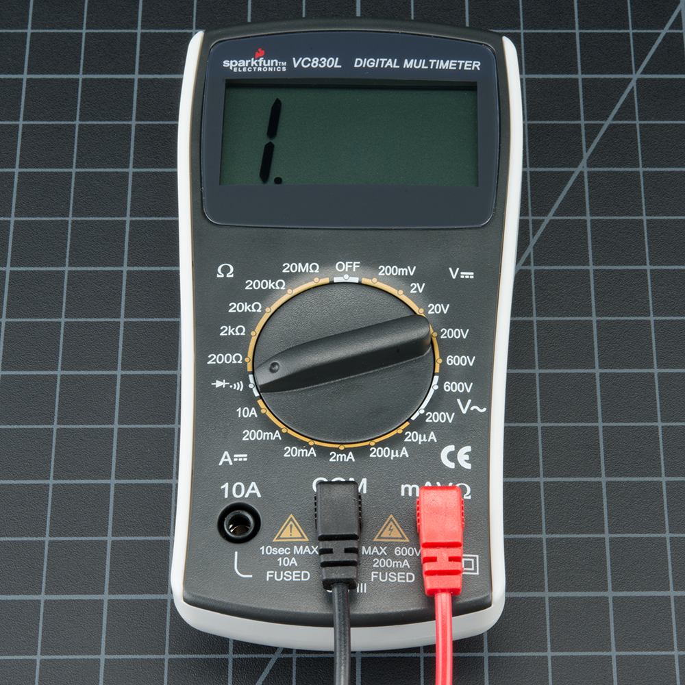
Begin by turning on your multimeter. You’ll notice several symbols and settings on the dial. For continuity testing, look for the symbol that resembles a sound wave or a diode, often marked with a “•)))” or similar icon. Ensure the multimeter is set to continuity mode, not resistance or voltage. This mode will emit a sound when a complete circuit is detected. Picture a time when you thought your circuit was perfect, but the silence revealed a break you hadn’t noticed.Preparing The Test Leads
Next, grab your test leads—these are the wires that connect to your multimeter. Typically, one is black and the other is red. Insert the black lead into the COM port and the red lead into the VΩmA port. Check the leads for any visible damage. Would you trust a frayed wire to give you accurate results? Make sure they are in good condition to avoid misleading readings. Once your leads are in place, touch them together. Your multimeter should beep, confirming they are functioning properly. This step mirrors a warm-up stretch before a workout, ensuring everything is in working order before you begin the task. Setting up your multimeter properly may seem like a small detail, but it lays the groundwork for successful continuity testing. Have you ever found yourself frustrated by an unexpected outcome, only to realize a simple setup mistake was the culprit? A little preparation can save you from such headaches, turning a potential problem into a straightforward solution.Conducting A Continuity Test
Conducting a continuity test is simple and essential for electrical work. It helps identify breaks in a circuit. A multimeter is the tool you need. Use it to check if electrical flow is uninterrupted. This can prevent future problems.
Testing Wires And Cables
Start by disconnecting power from the circuit. Set your multimeter to the continuity setting. Touch one probe to each end of the wire. A beep or zero reading means the wire is continuous. If there is no sound or an infinite reading, the wire is broken. This test ensures wires are intact.
Testing Switches And Components
Ensure the switch is off before testing. Connect one probe to each terminal of the switch. Flip the switch to the on position. A beep means the switch is working. No sound indicates a faulty switch. For components, remove them from the circuit. Place probes on each terminal. A sound confirms the component is good. No sound suggests it needs replacing.
Interpreting Results
Testing for continuity with a multimeter involves checking if electrical current flows smoothly through a circuit. Set the multimeter to continuity mode, then connect its probes to the circuit’s endpoints. A continuous beep or low resistance reading indicates proper connectivity.
Interpreting results from a multimeter can be surprisingly straightforward, once you grasp the basics. Have you ever been frustrated trying to figure out why your electronic device isn’t working? Understanding how to read continuity results can be the key to solving these puzzles. When you test for continuity, you are essentially checking if electricity can flow through a circuit without any interruptions. Let’s dive into how you can identify continuity and troubleshoot non-continuity issues.Identifying Continuity
Continuity means that the electrical path is complete, allowing current to flow freely. When your multimeter beeps or shows a zero resistance reading, you have continuity. This is a good sign—it means the circuit is intact. Imagine testing a wire; if there’s a beep, the wire is unbroken. Wouldn’t it be great if all components were as cooperative? Sometimes, though, you might get partial continuity, which indicates some resistance. Keep an eye out for readings that aren’t zero but are still low. This might suggest a weak connection that could cause problems down the line.Troubleshooting Non-continuity
Non-continuity is like a roadblock in your circuit—it stops the flow of electricity. If your multimeter is silent or shows a high resistance reading, there’s a disruption somewhere. Don’t panic! Start by checking connectors and joints—they are often the culprits. Is the component you’re testing supposed to have continuity? For instance, resistors shouldn’t beep since they resist the flow of electricity. If you’re testing a wire or a switch, however, non-continuity might indicate a break or corrosion. Sometimes, it’s all about the little things. Consider cleaning contacts or replacing faulty parts. This often resolves non-continuity issues. Have you ever had a device work perfectly after tightening a loose connection? Those small actions can make a big difference. Understanding these results empowers you to make informed decisions about repairs. So next time your multimeter gives you the silent treatment, you’ll know exactly what to check.Expert Tips And Tricks
Testing for continuity with a multimeter ensures electrical connections are intact. Set the multimeter to continuity mode. Place the probes on the circuit points. A beep or reading confirms a continuous path.
Testing for continuity with a multimeter can seem daunting. Yet, mastering this skill brings confidence in your electrical projects. With expert tips and tricks, you can ensure accurate readings. This section unveils secrets to avoid common pitfalls. Also, it guides you to achieve precise results.Common Mistakes To Avoid
Many beginners face challenges with multimeters. One frequent mistake is using the wrong probe ports. Ensure the probes are correctly connected. Another error is setting the wrong function on the multimeter. Always select the continuity setting. Touching the probes directly is another common issue. Avoid this to prevent incorrect readings. Lastly, failing to check battery levels can mislead your results. Keep the multimeter’s battery in good condition.Ensuring Accurate Readings
Accuracy is vital in continuity testing. Start by calibrating your multimeter regularly. This maintains its precision. Use clean probes for better contact. Dirt can interfere with the connection. Maintain a steady hand while testing. Movement can affect the reading. Double-check connections and settings before starting. This step ensures you have the right setup. Lastly, practice makes perfect. Familiarize yourself with the multimeter’s features and functions. This boosts confidence and enhances accuracy.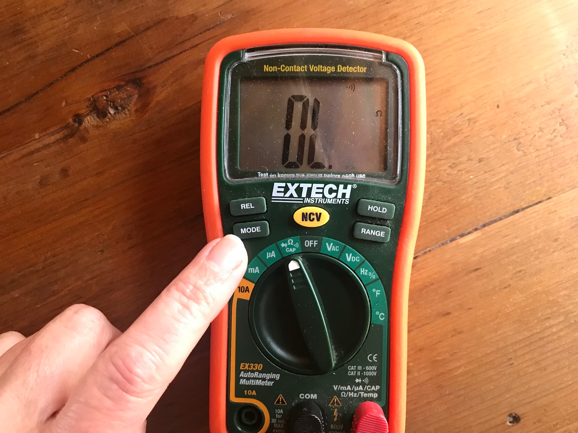
Credit: chibitronics.com
Applications Of Continuity Testing
Testing for continuity with a multimeter checks if electrical circuits are complete without interruptions. A probe measures resistance, signaling continuity with a beep or display change. Essential for troubleshooting, this process ensures components like wires and switches work properly, avoiding failures.
Testing for continuity with a multimeter is not just a technical skill; it’s a gateway to understanding the electrical world around you. Whether you’re a professional electrician or a DIY enthusiast, knowing the applications of continuity testing can save you time, money, and frustration. This process is all about ensuring that electrical circuits are complete, which is vital for any functioning electrical system.Electrical Repair
Continuity testing is a crucial step in electrical repair. Imagine you’re fixing a broken lamp. You suspect the issue might be a break in the wiring. By using a multimeter to test for continuity, you can confirm if the electrical path is intact or broken. This technique can also help you troubleshoot faulty light switches or malfunctioning outlets. If you’ve ever experienced flickering lights, continuity testing can reveal if a loose connection is the culprit. It’s a straightforward way to pinpoint problems and ensure safety in your home.Diy Projects
For those who love DIY projects, continuity testing is an invaluable tool. Whether you’re building a custom gaming PC or installing a car stereo, ensuring that all connections are solid is essential. Have you ever spent hours assembling something only to find it doesn’t work because of a missed connection? A quick continuity test can prevent such frustrations. Continuity testing isn’t just for avoiding mistakes; it can also fuel creativity. When designing your own electronics, it allows you to experiment with confidence. You can test new configurations without worrying about incomplete circuits. This empowers you to innovate and bring your DIY visions to life. Are you ready to add continuity testing to your skill set? It’s a small step that can make a big difference in your electrical projects. Whether fixing or creating, knowing that your connections are reliable can be incredibly satisfying.
Credit: www.wikihow.com
Frequently Asked Questions
What Is The Symbol For Continuity On A Multimeter?
The continuity symbol on a multimeter is typically a sound wave or diode symbol. It often looks like a series of curved lines or a triangle with a line. Use this setting to check the continuous path of electricity in circuits.
What Is The Correct Ohm Reading For Continuity?
A correct ohm reading for continuity is typically between 0 to 1 ohm. This indicates a good electrical connection. A higher reading suggests poor continuity or a broken circuit. Always ensure your multimeter is set correctly for accurate readings.
Which Setting Will You Use When Using A Multimeter To Do A Continuity Test?
Use the multimeter’s continuity setting, often indicated by a diode symbol or sound wave icon. Connect the probes to the circuit or component. The multimeter will beep if continuity exists, indicating a complete path for current flow. Always ensure the device is off and unplugged before testing.
What Is Ol On A Multimeter?
“OL” on a multimeter means “Open Loop” or “Over Limit”. It indicates an open circuit or a measurement beyond the meter’s range. This occurs when there’s no continuity or the measured value exceeds the multimeter’s capacity. Always ensure proper connection and setting for accurate readings.
Conclusion
Testing for continuity with a multimeter is simple. Follow these steps for accurate results. Always ensure safety first. Disconnect power before testing. Use the multimeter’s continuity setting. Listen for the beep. A beep means good connection. No beep? Check for breaks in the circuit.
Practice makes it easier. Soon, you’ll test like a pro. With patience, anyone can do it. Proper testing ensures electrical safety. Keep your tools ready. Stay informed and practice regularly. Your confidence will grow. Multimeters are handy tools. They make electrical tasks safer and easier.
Happy testing!